VFD Ornament
PROLOGUE
This is my VFD clock that is fun and silly. In it you’ll be able to solder a VFD tube two digit clock that connects to your WiFi network and NTP syncs to keep the current time. It’s all programmed in Arduino, so it should be much more accessible for you to customize. Oh, and then there’s the 6 NeoPixels that you can use for your own amusement. I’ll walk you through the build process for how I like to construct these devices. Let’s get tootin!
Let’s get started!
Material Needed/Suggested:
Soldering Iron - Chisel Tip
Solder - (60/40)
Solder Flux - (No clean flux)
Tweezers
Tape
Circuit board holder
Voltmeter
Step 1 (The Hardest Part): Setup your Arduino IDE to support the WeMos D1 Mini. There are tons of how-to’s on this topic. Here are two links that will get you started in this endeavor.
https://www.instructables.com/id/Wemos-ESP8266-Getting-Started-Guide-Wemos-101/
https://www.embedded-computing.com/embedded-computing-design/getting-started-with-the-wemos-d1-mini-esp8266-dev-board
You will also need to make sure you have the following libraries installed, available here:
https://github.com/arduino-libraries/NTPClient
https://github.com/adafruit/Adafruit_NeoPixel
Once you get this setup, plug in your WeMos and attempt to compile and load the code to the device. Don’t forget to set your SSID and passphrase. If all worked, check your DHCP lease tables for a WeMos ESP device. If it went wrong, please let me know so I can update the instructions and FAQ.
Code available here:At my git!
Step 2 (Solder the Caps): On the back of the board are two places for the capacitors. They have no orientation and are the same value. They are also the only two of the same component in the bag. Go a head and solder these two on the back of the board.
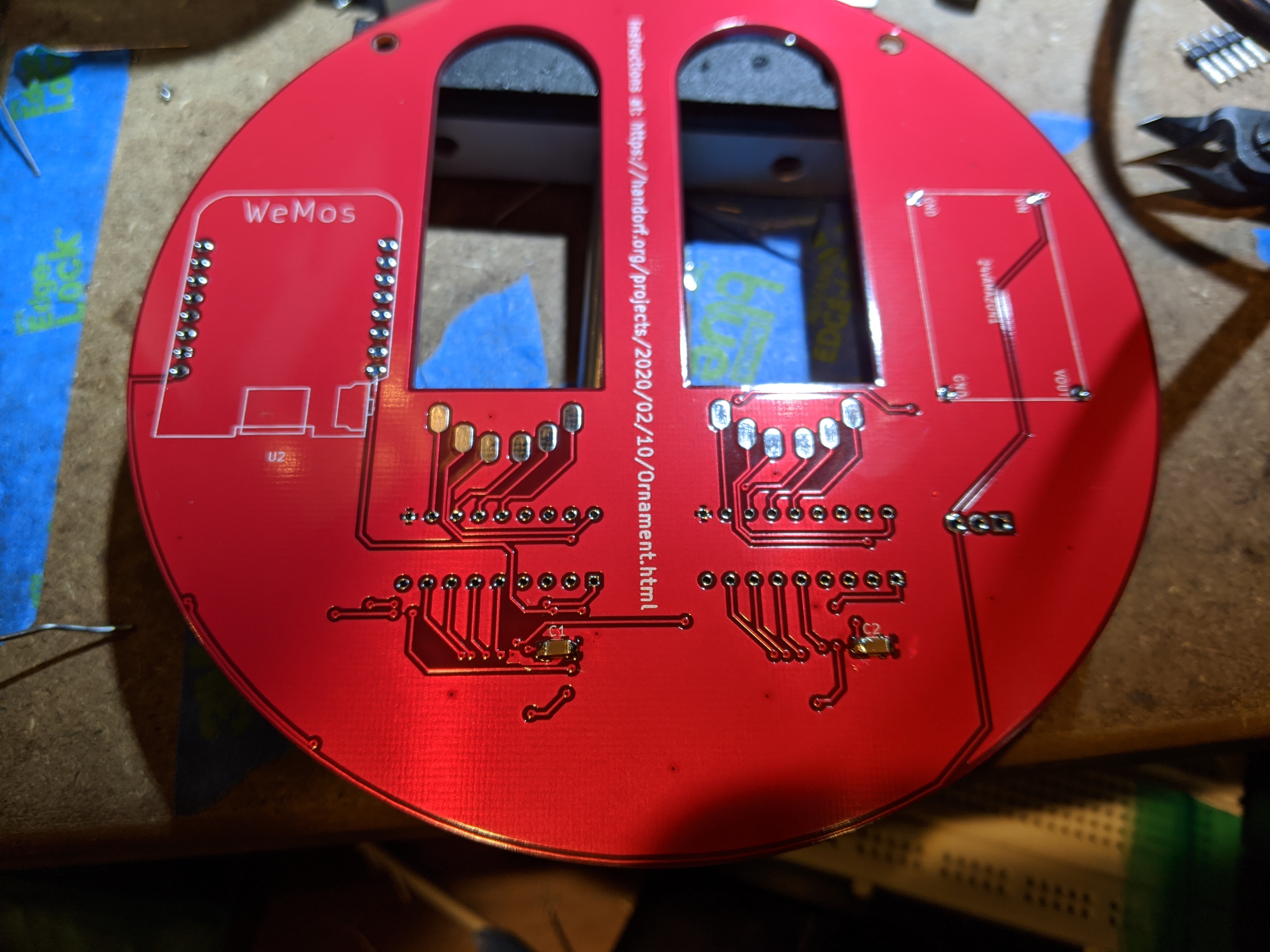
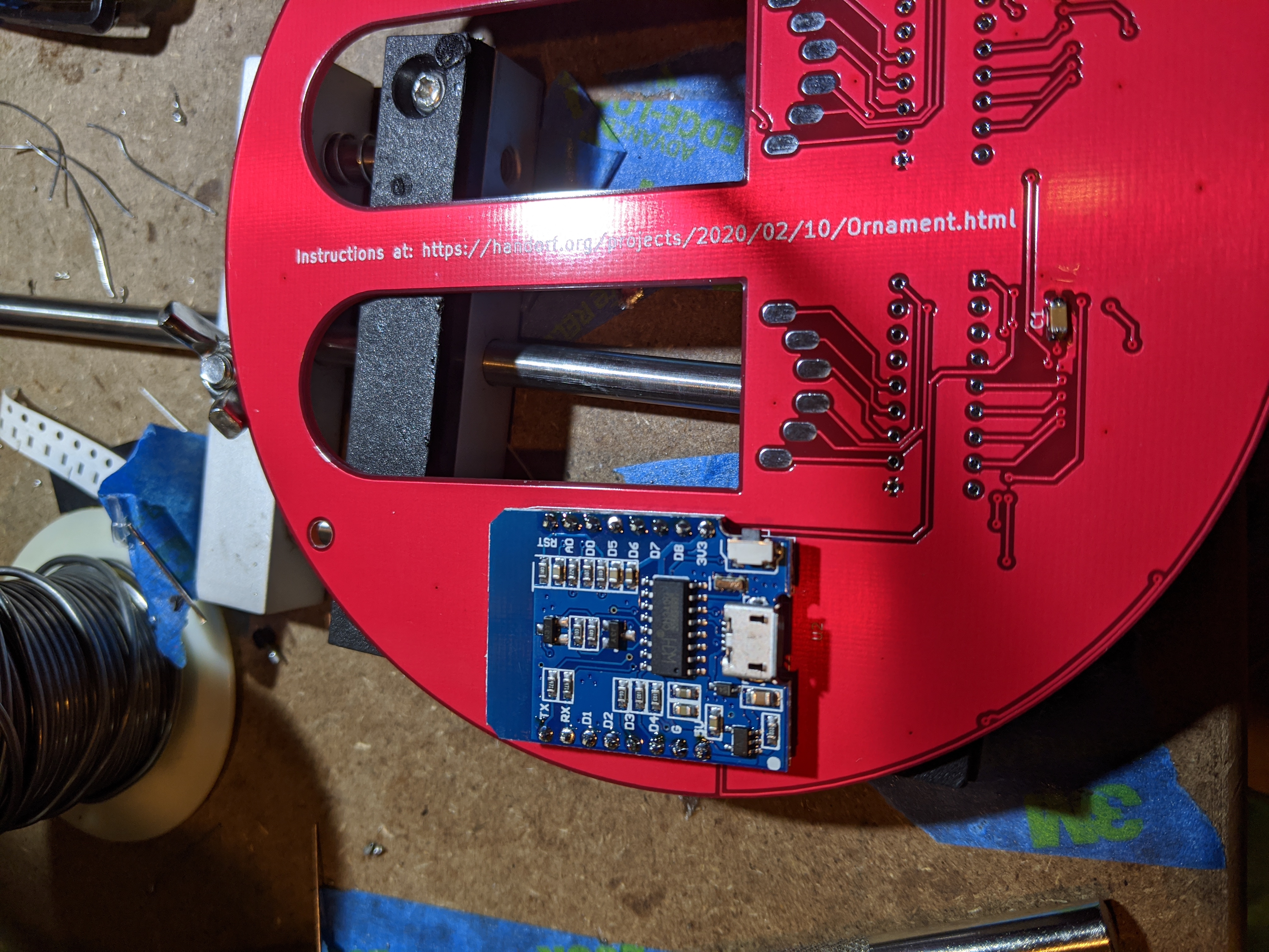
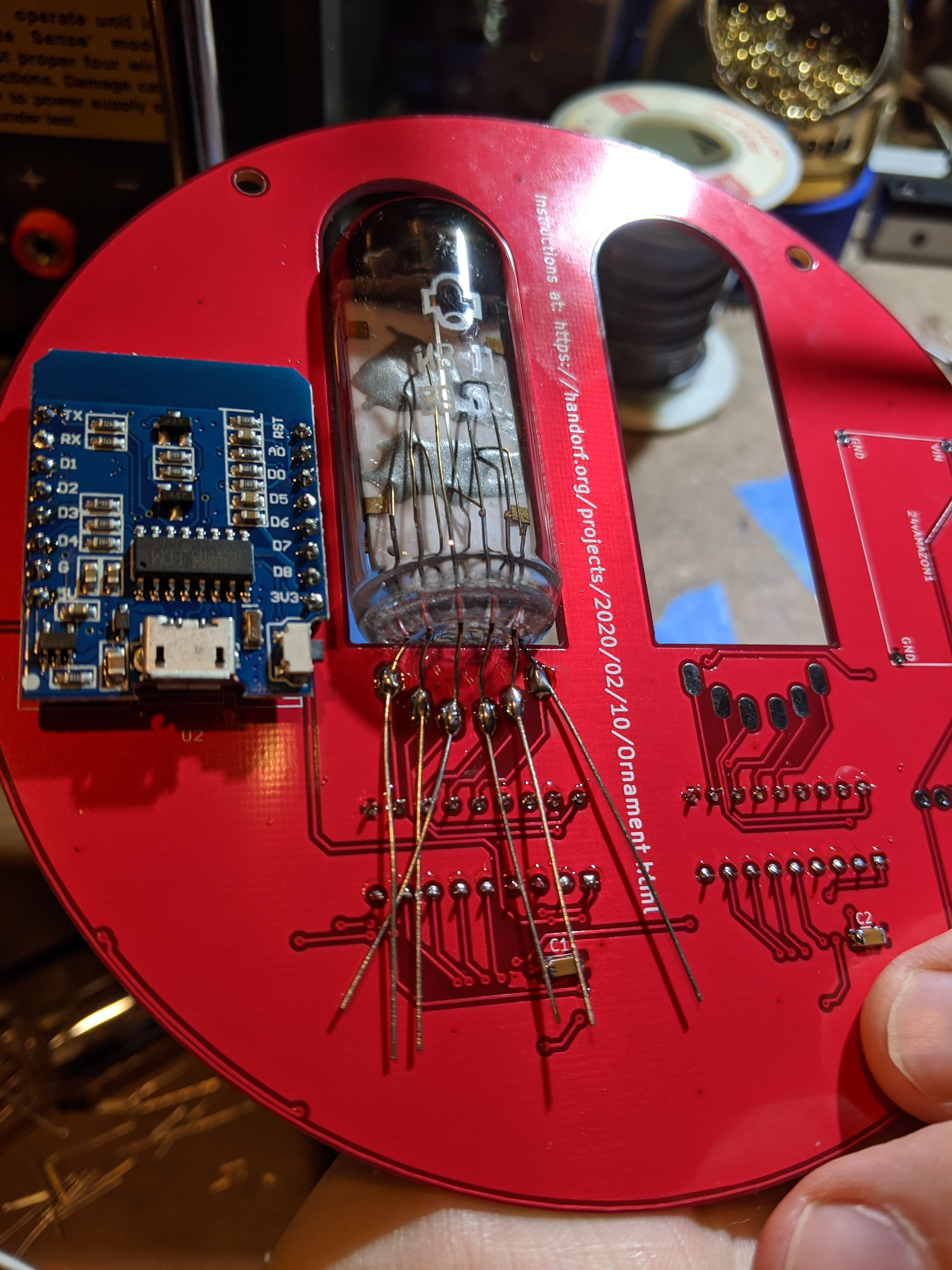
Step 3 (Solder the WeMos): I liked putting the long pins through the board and having the short ones to then place the WeMos ontop of on the back of the board. I soldered the four corners of the WeMos, making sure my alignments were to my liking, and then soldered the rest of the pins of the WeMos. I then flip the whole board over, solder the pins down, trim them, and then reflow them to make it a little cleaner.
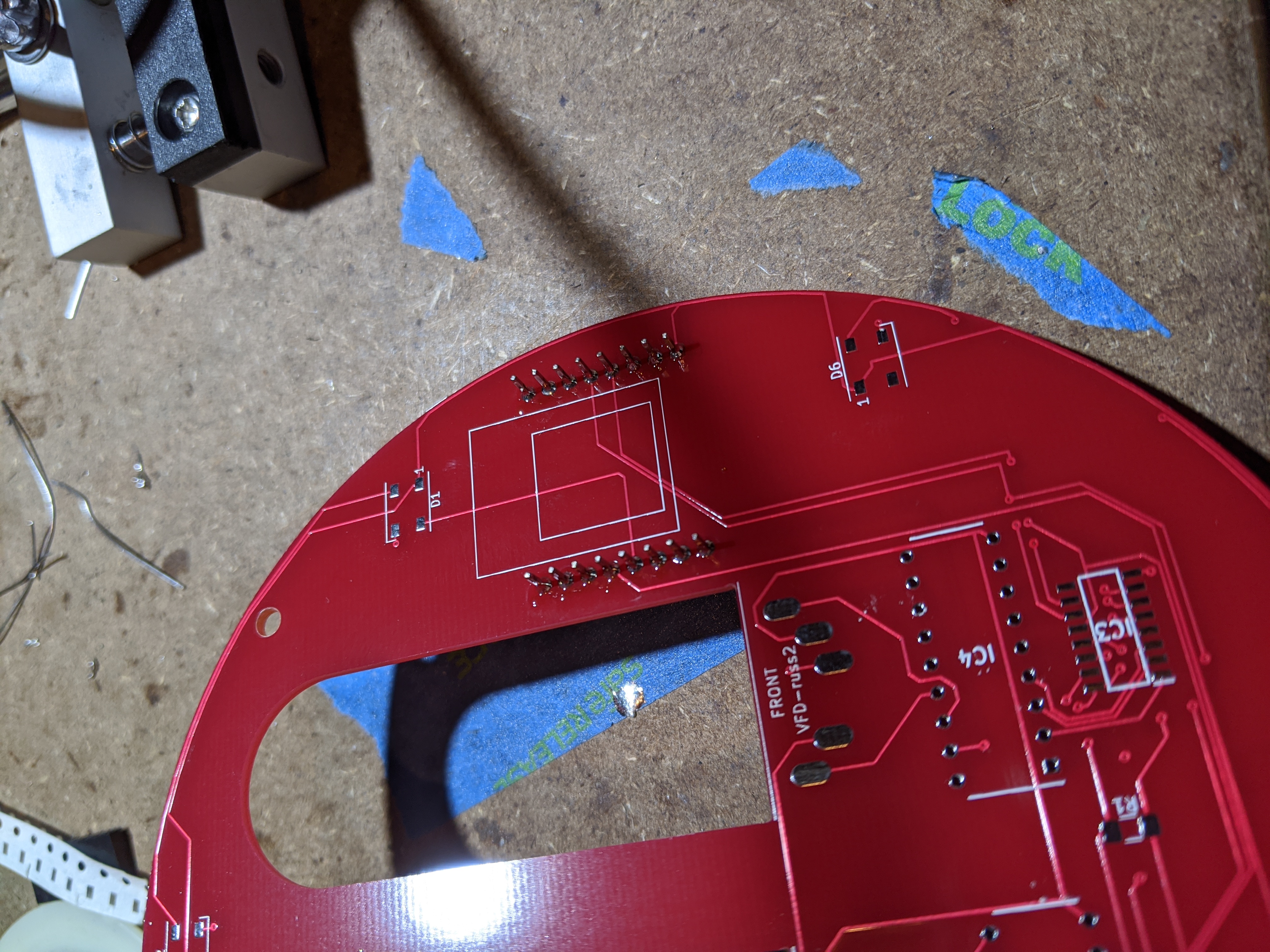
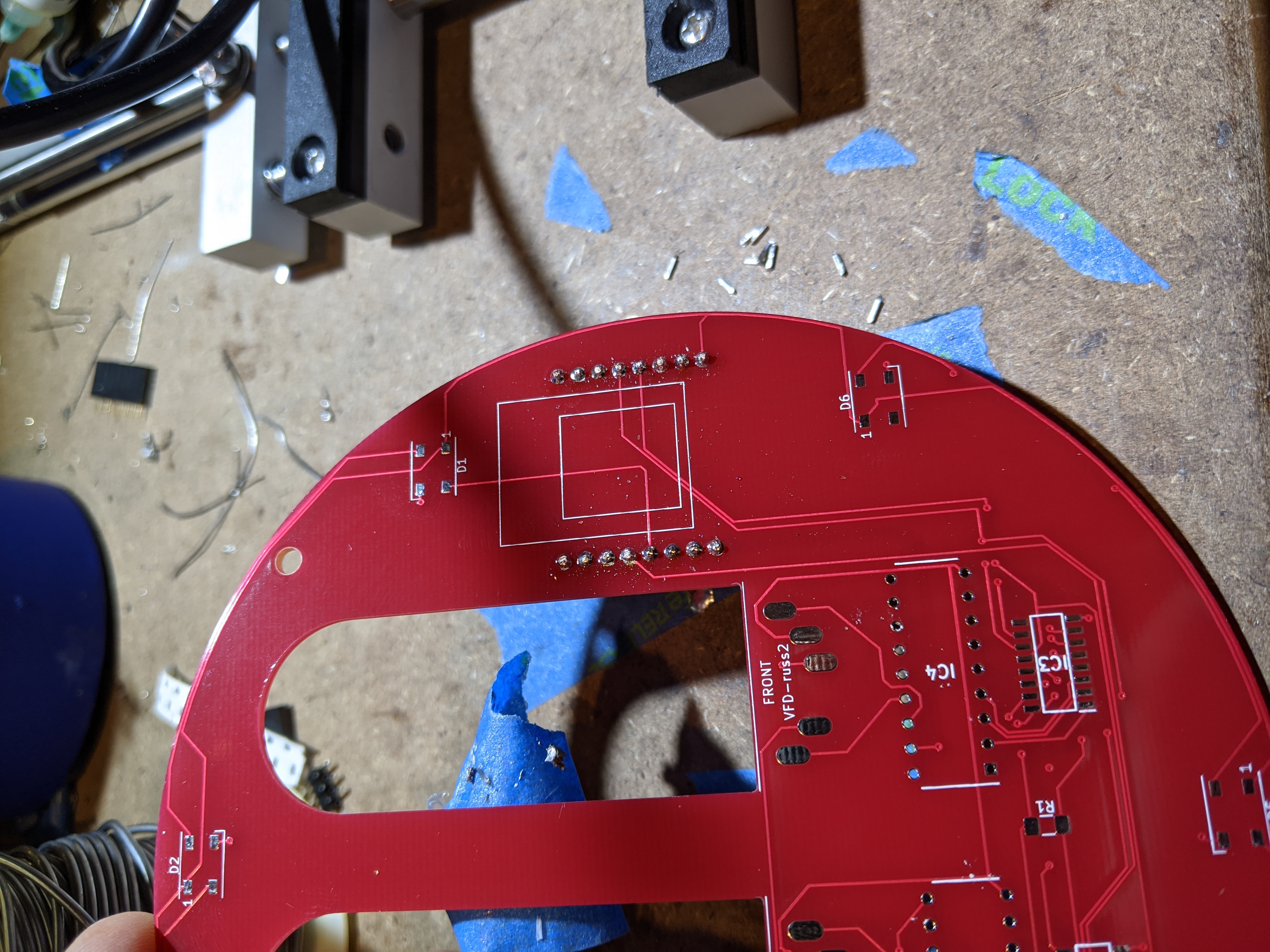
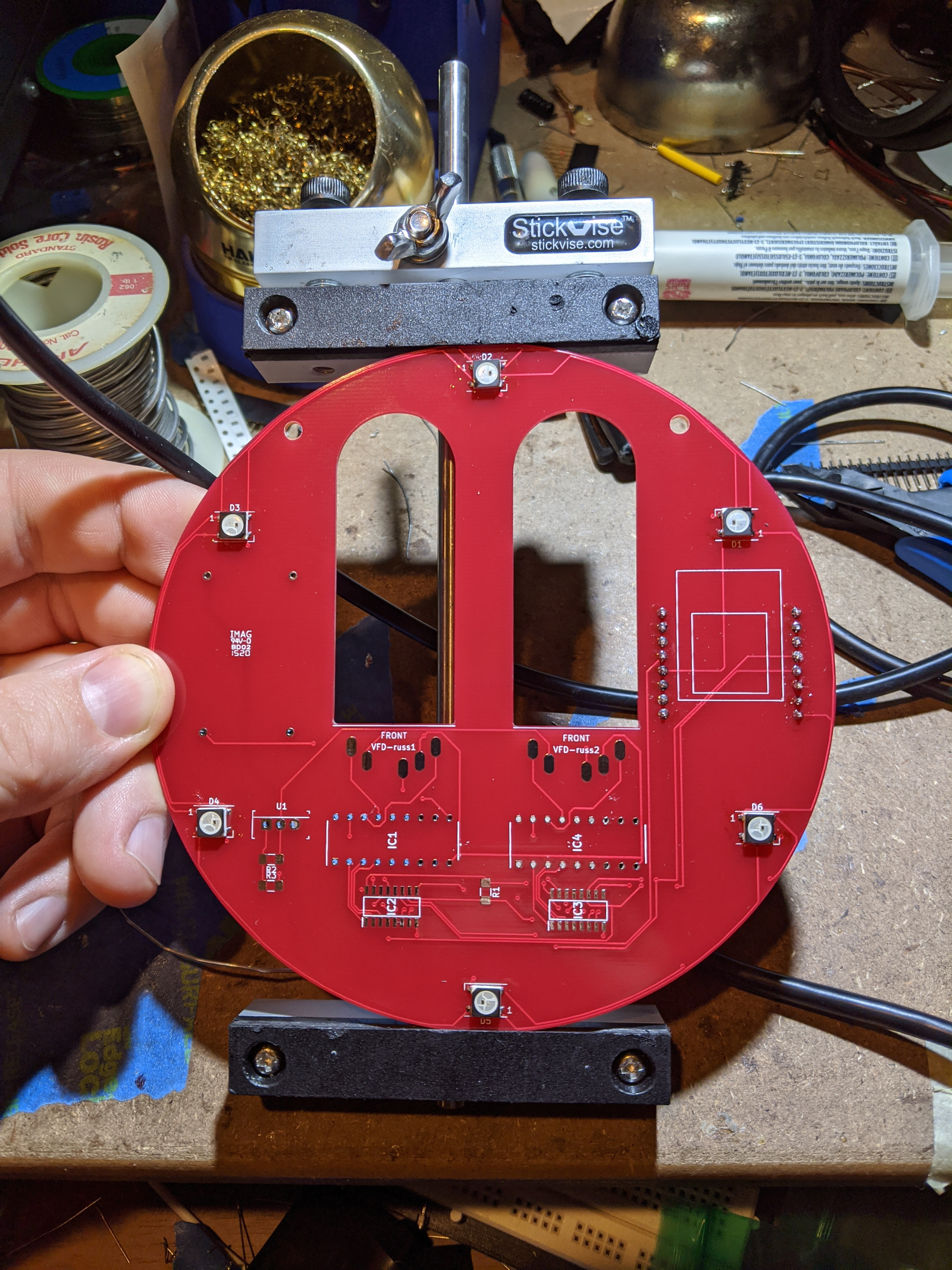
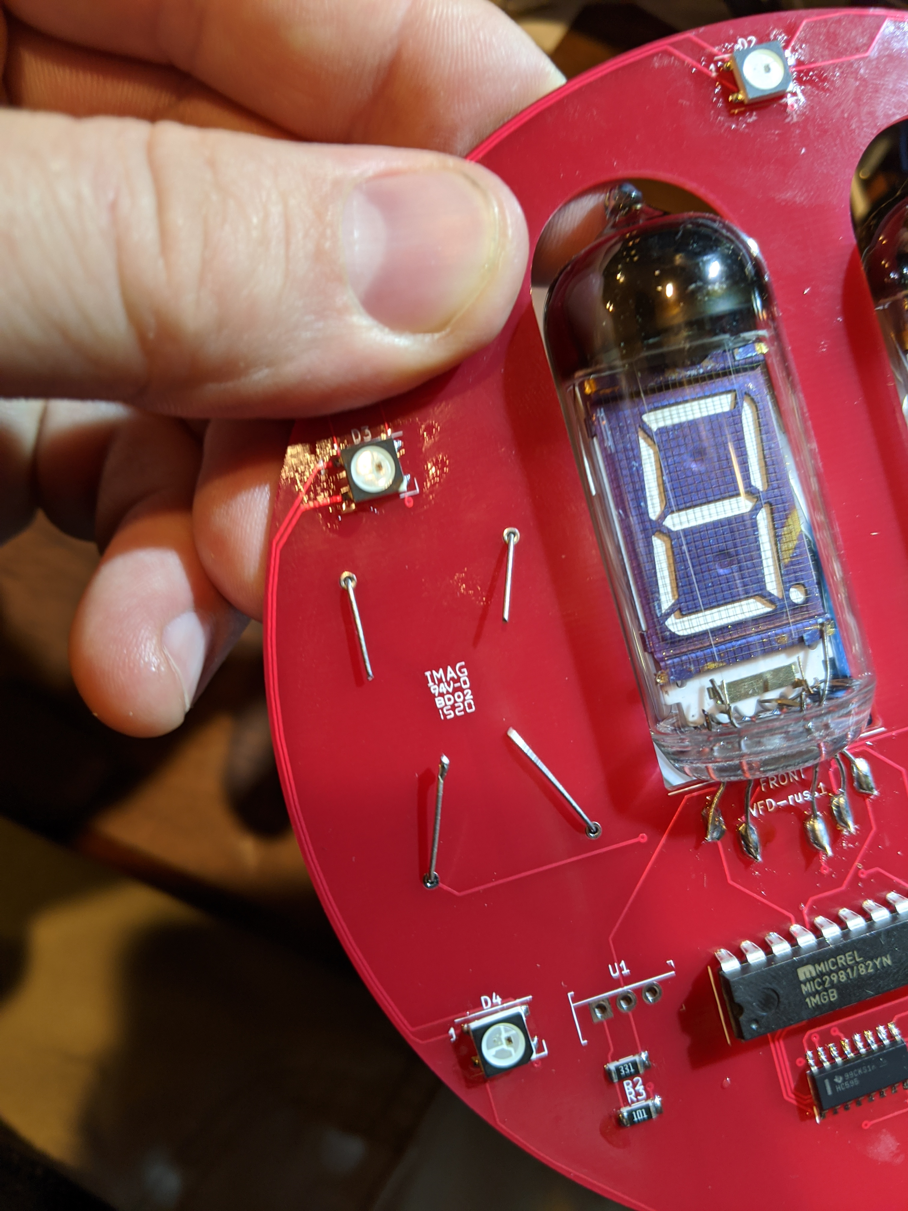
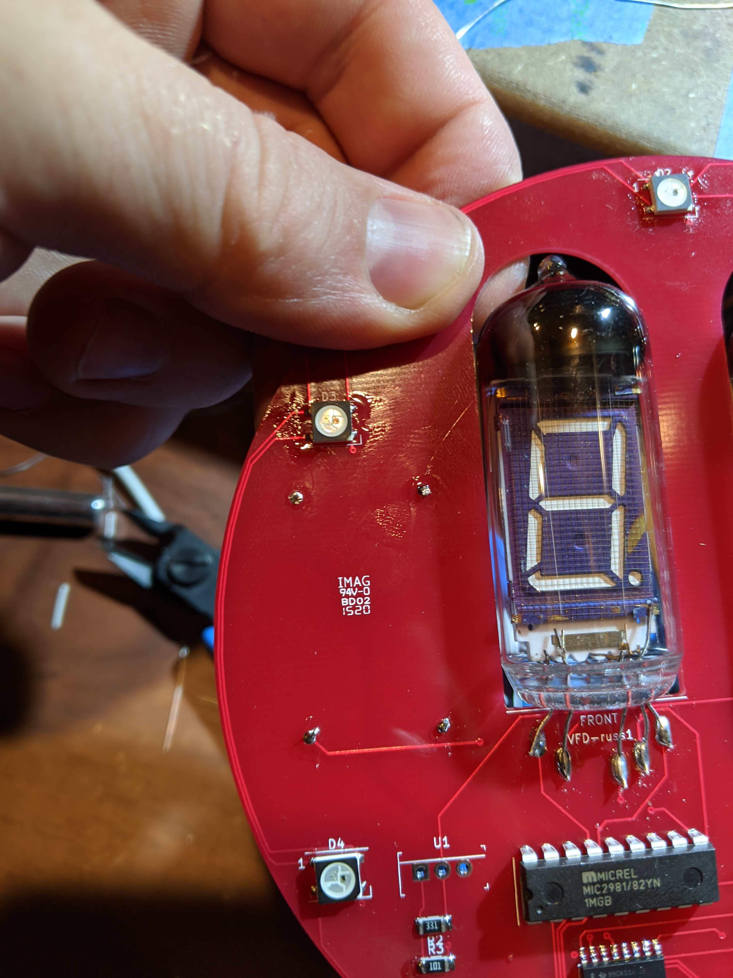
Step 4 (Solder the NeoPixels): There are 6 neopixels on the board. Go ahead and place flux on the pads for the neopixels on the circuit board. The orientation for each pixel should be that the white corner is away from the PIN 1 notation on the circuit board. The flux will help wick the solder up to the side of the LED and make contact with the pad. You can use tape, tweezers or your fingers to hold down each LED as you solder it. I found it useful to solder two pins on one side of each LED at a time, spin the board around, and then solder the other two pins after ensuring the LEDs were aligned and square.
Step 5 (Power Test): Plug in some power into the WeMos. All six NeoPixels should slowly turn on and off, like a second hand moving around a clock. Remember that they are chained. The first pixel is right above where the WeMos is and moves counter clockwise around the board. If there is a problem with a chain of them, debug them in a counter clockwise order. Once they all light, move onto the next step!
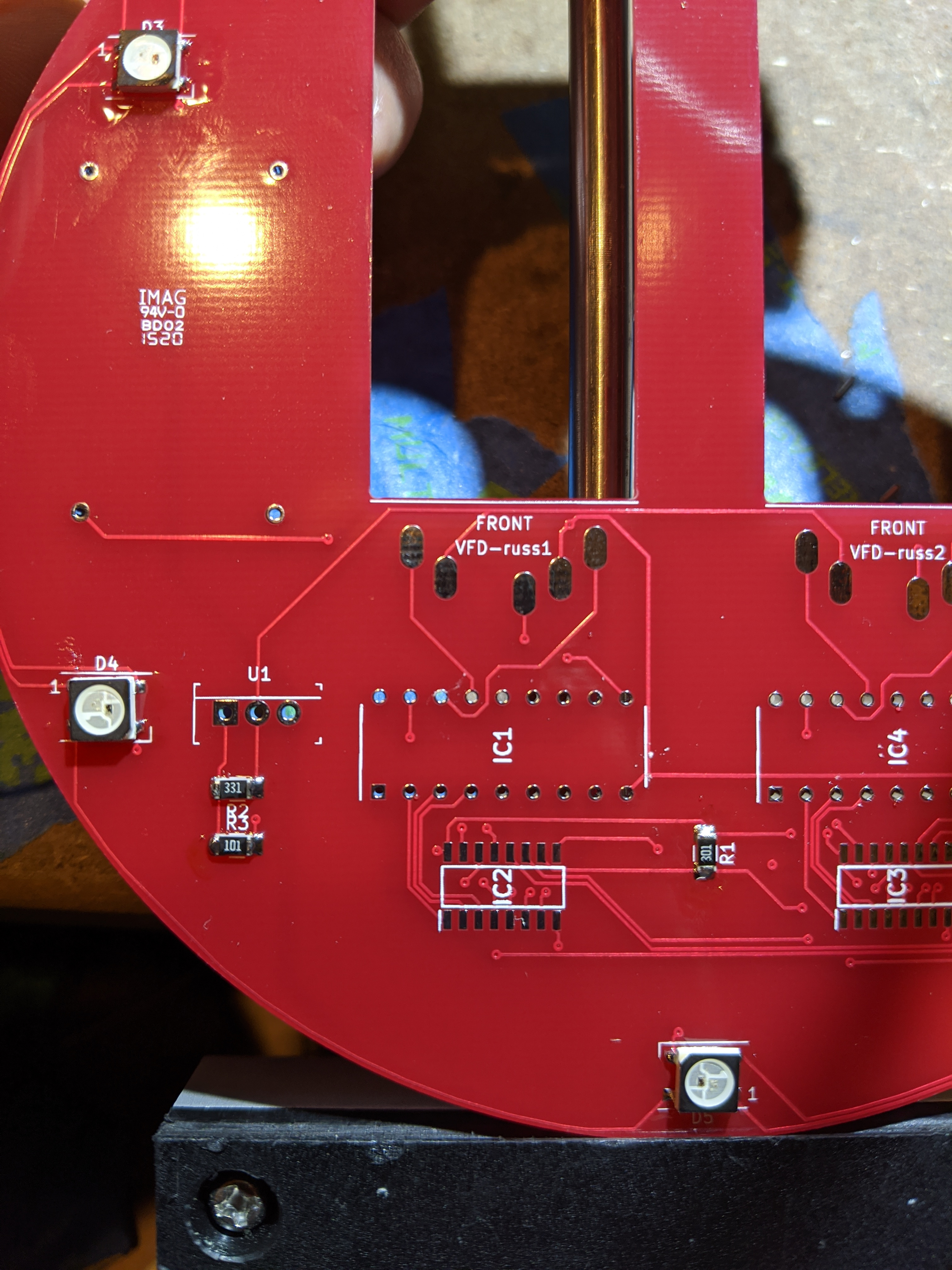
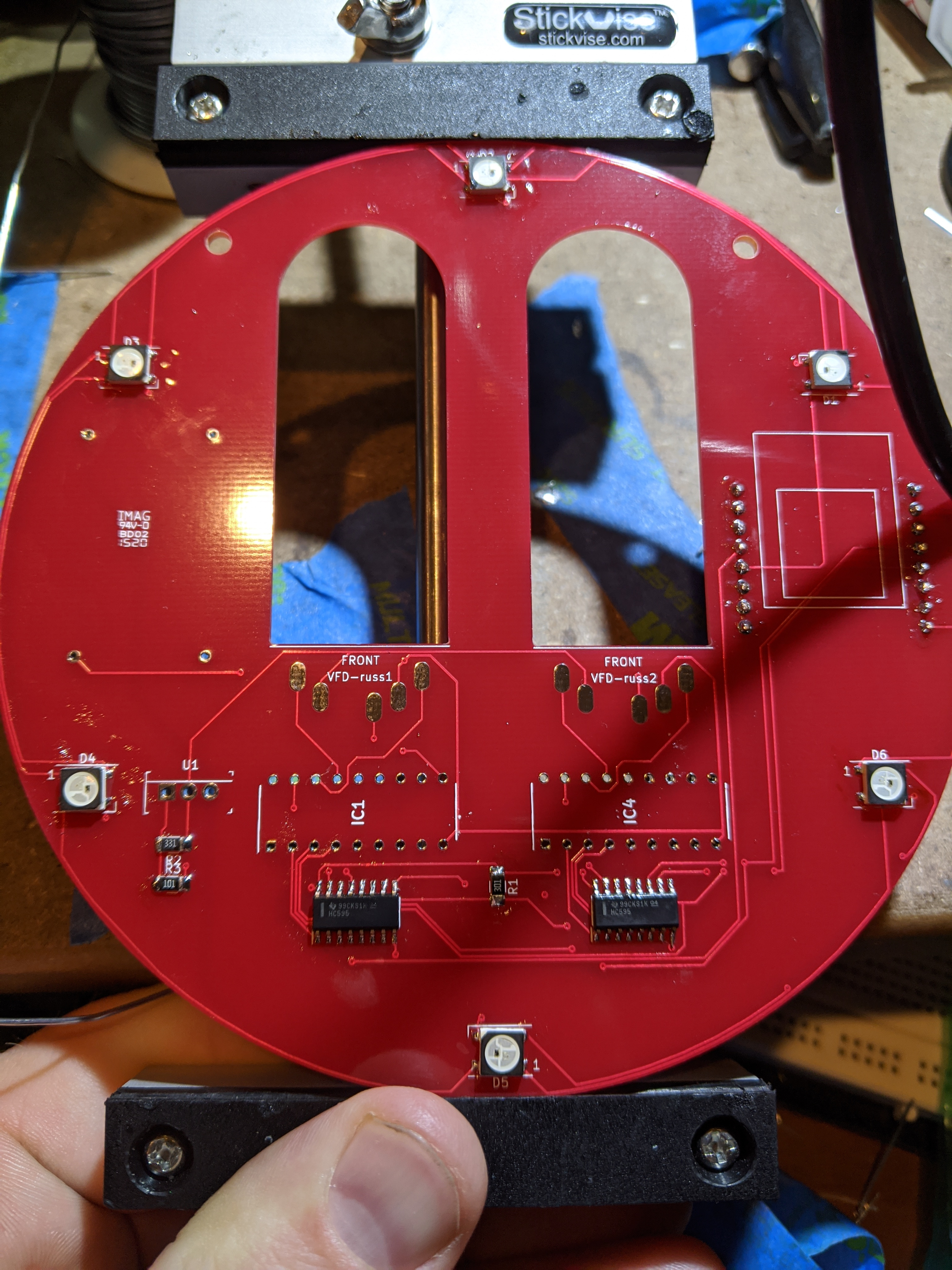
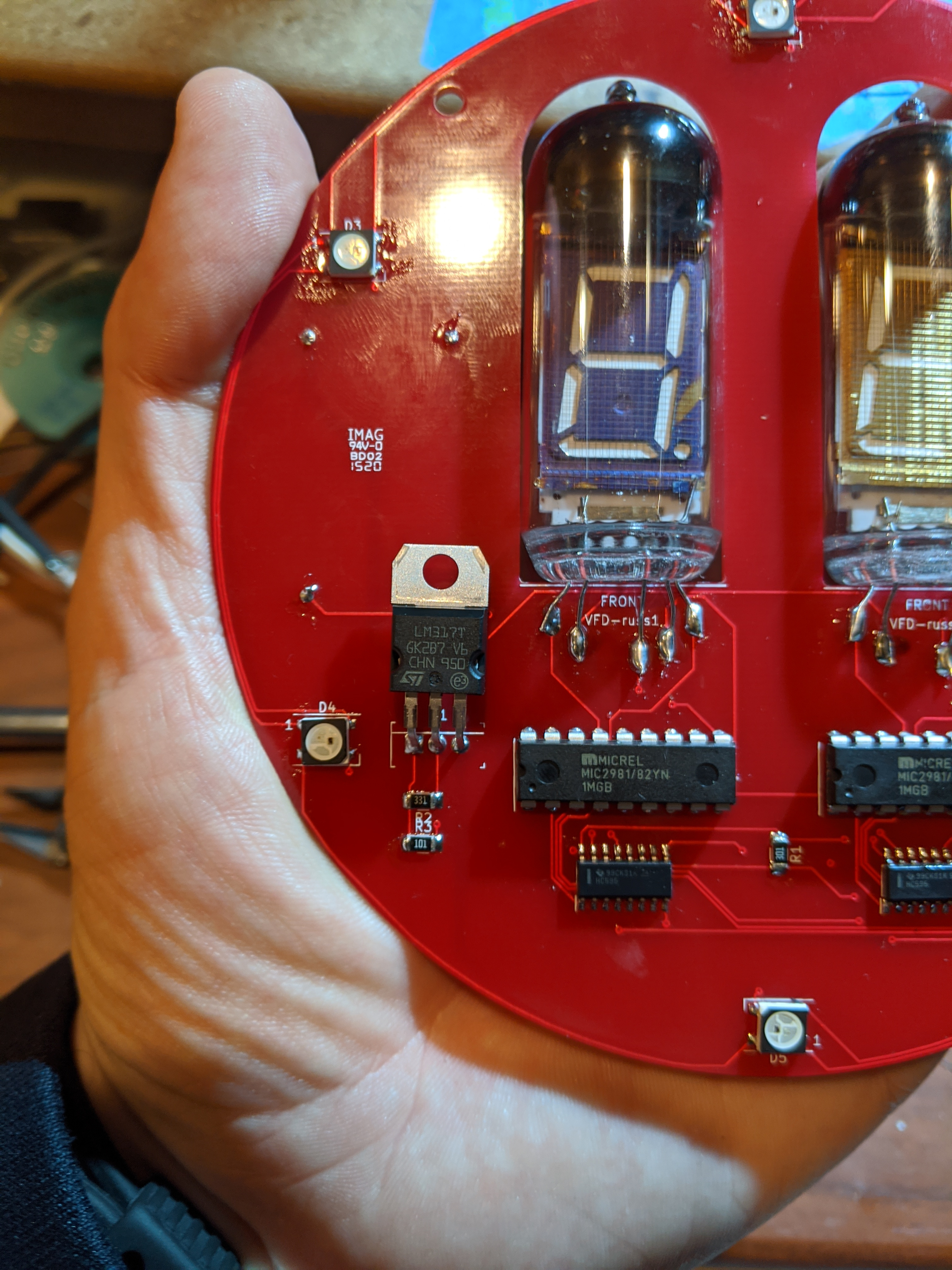
Step 6 (Shifters and Such): Place some flux on the pads for the SMD shifters. The line (or dot) on them should be facing left. I like to solder just one corner pin to set them on the pads, and then flow solder across; this way I can fix any misalignment before it becomes difficult to repair. After those are done, I solder in the PTH chips, notches on the left side. Solder on the three resistors. R1 is 301, R2 is 331, and R3 is 101.
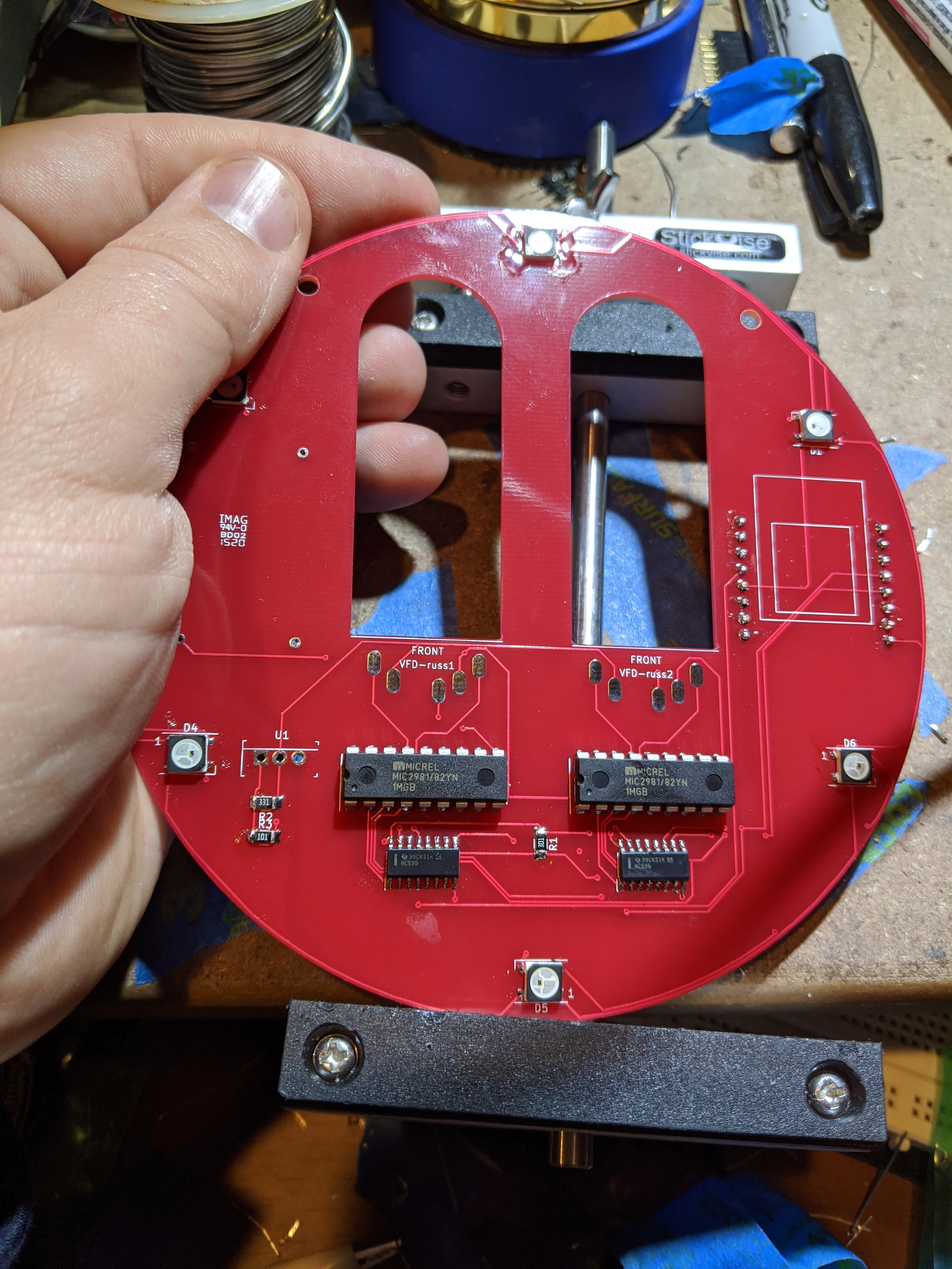
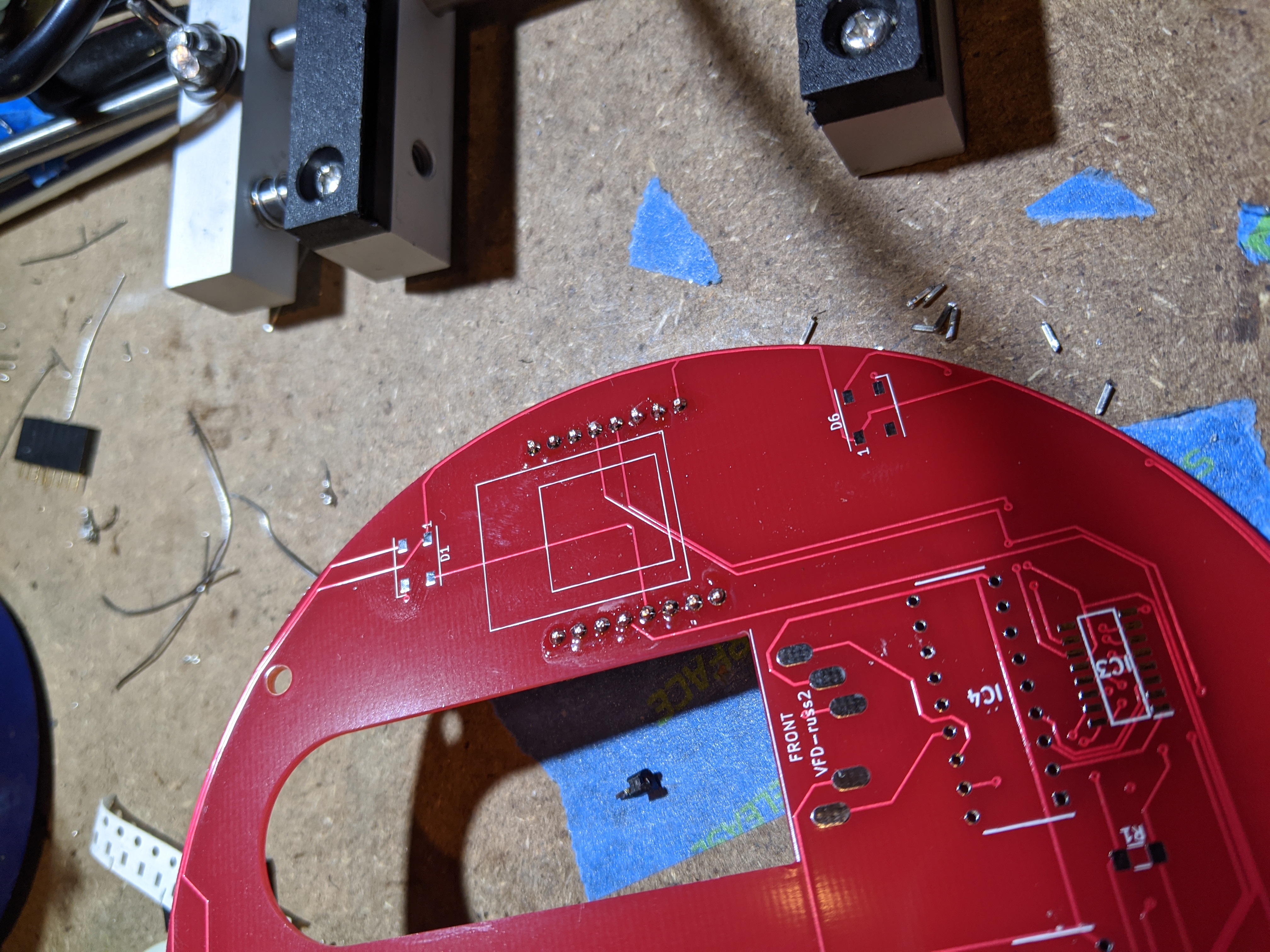
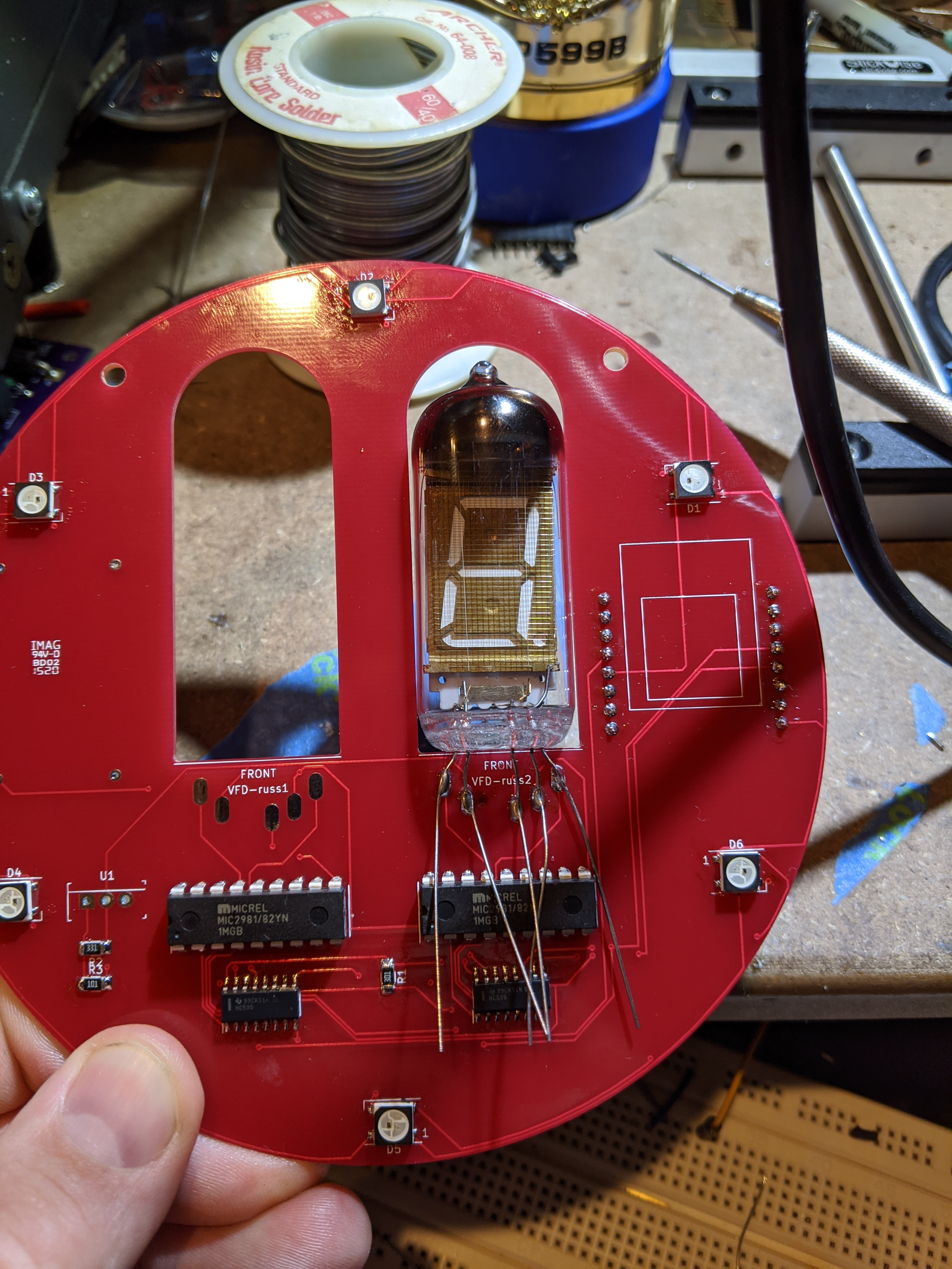
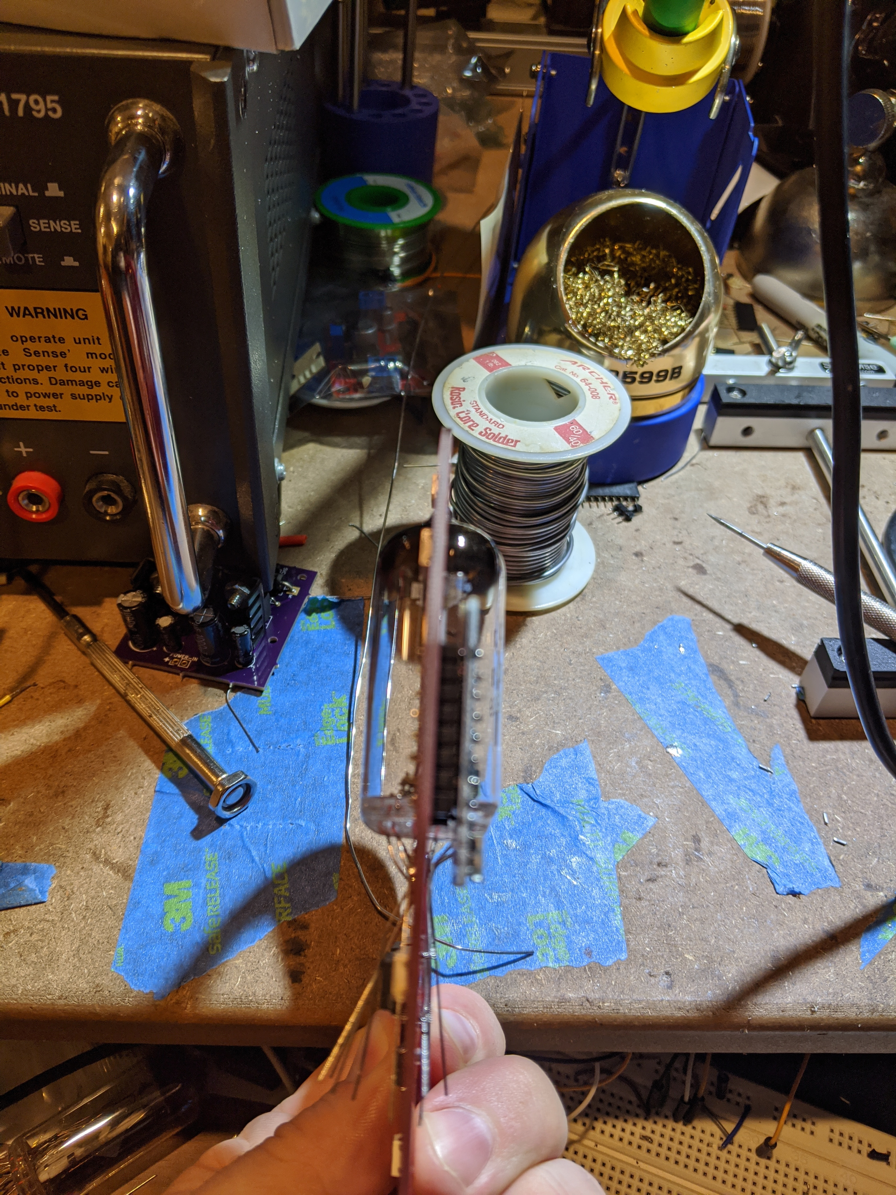
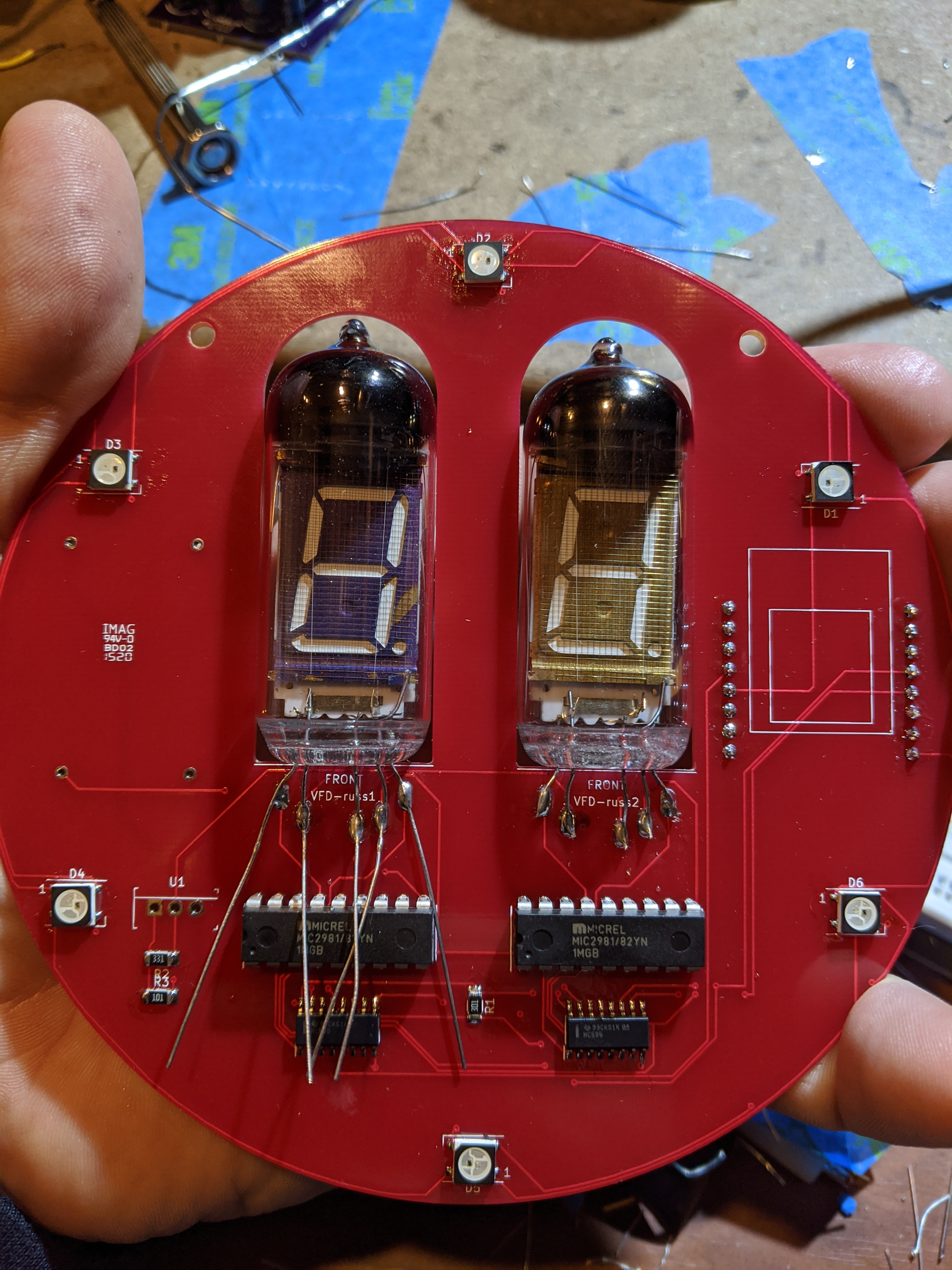
Step 7 (VFD): 5 pins in front, the rest in the back (electrical mullet), and straddle the bulb flat against the board. Hopefully the pictures below explain best to do. Once soldered, slip off the excess.
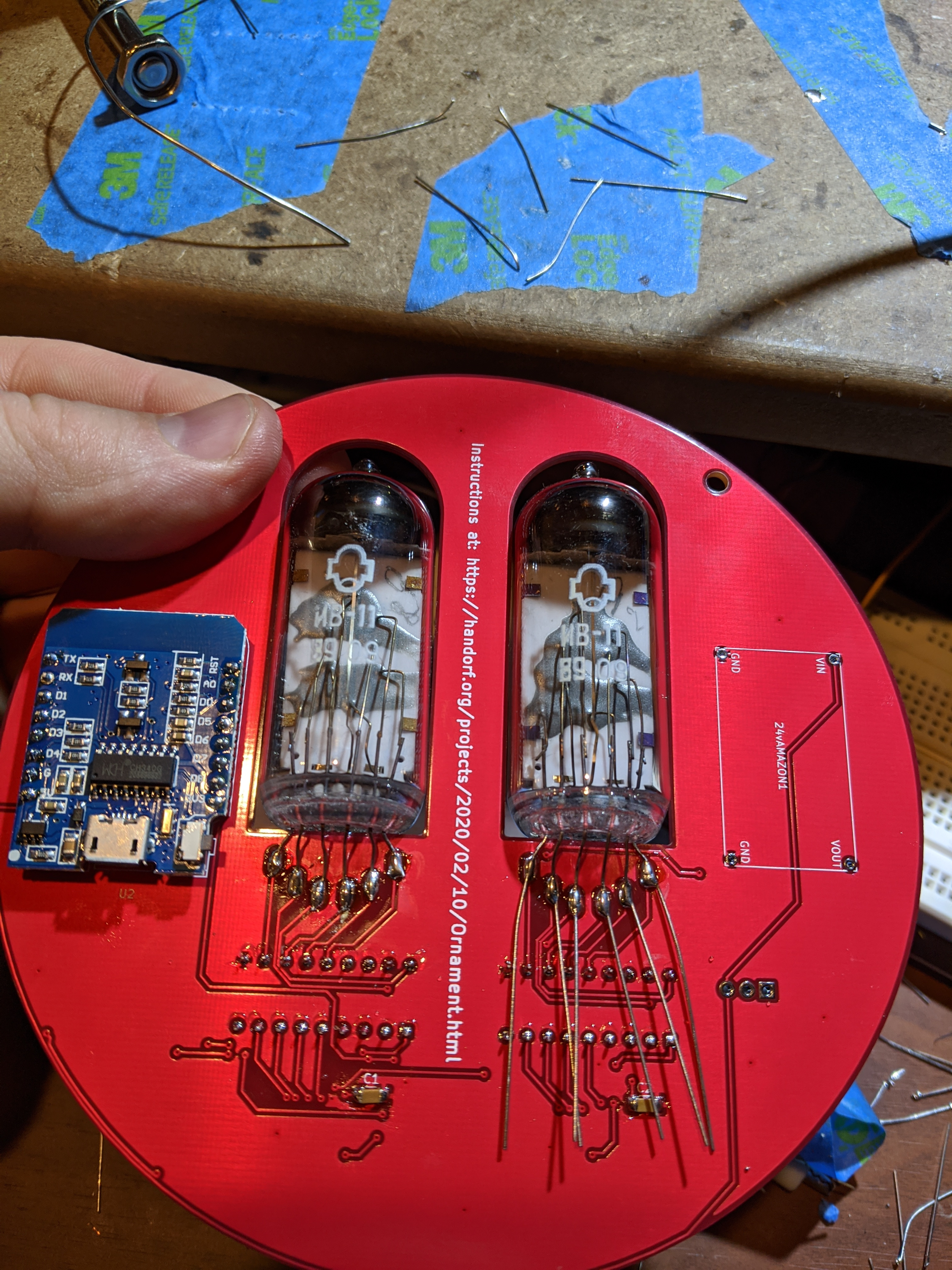
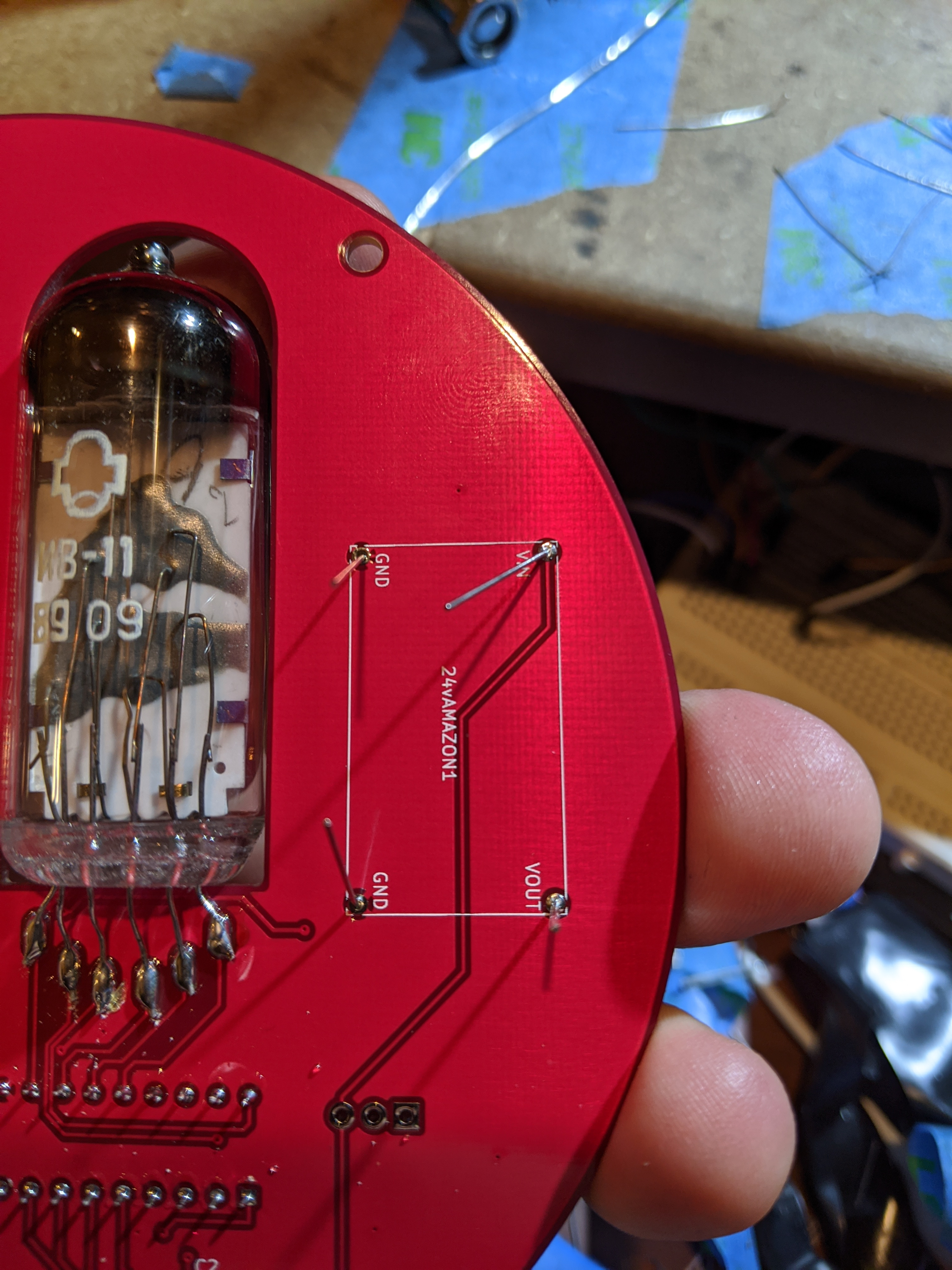
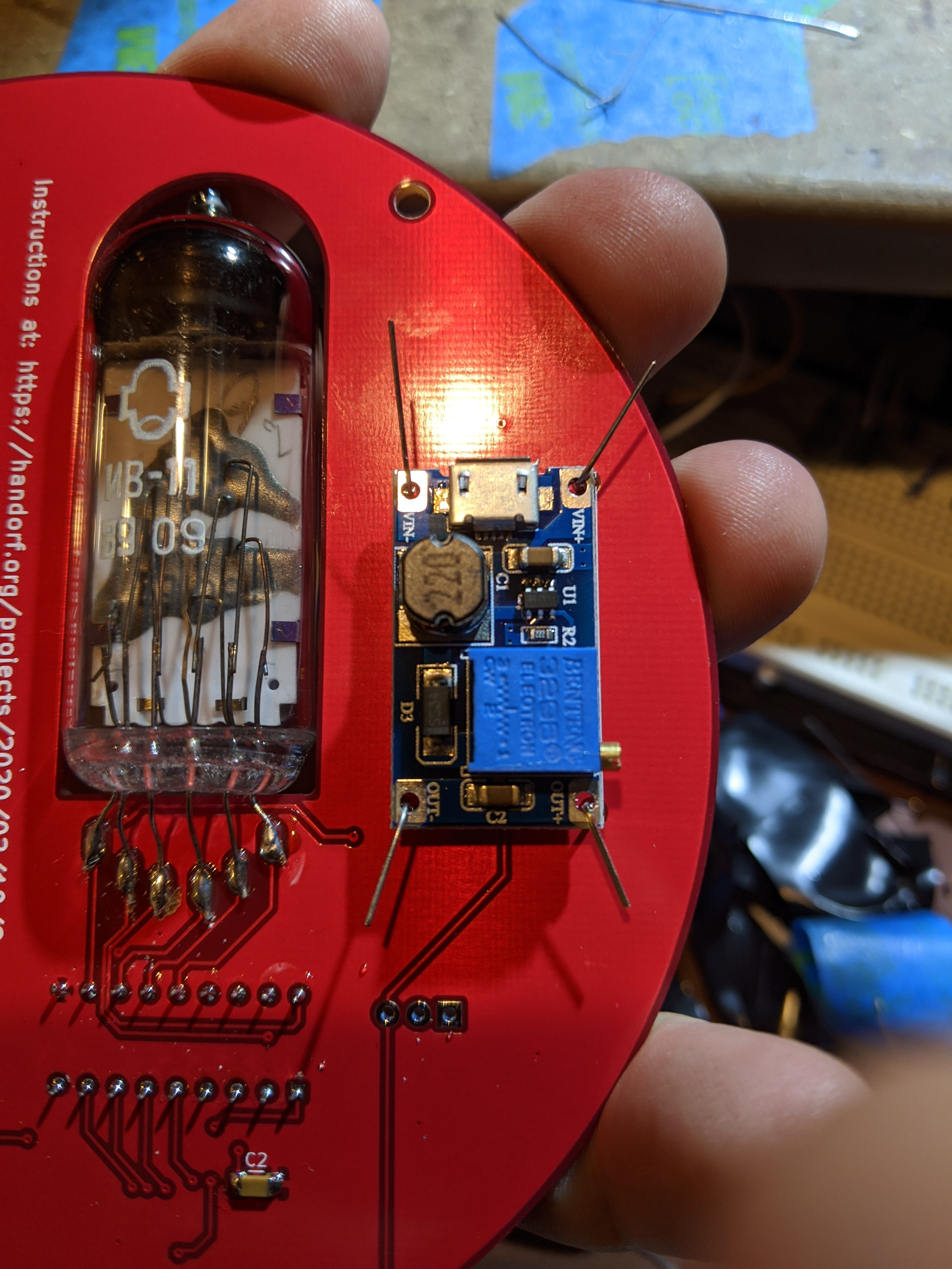
Step 8 (Boost Power): Take the boost power converter, plug it into a USB powers source and clamp on the voltmeter. Spin the variable resistor until you get to 20VDC. Once set, solder it to the back of the board as depicted below. You can use the left over leads from the VFD tube to help with this. The board is meant to "hover" over the PCB.

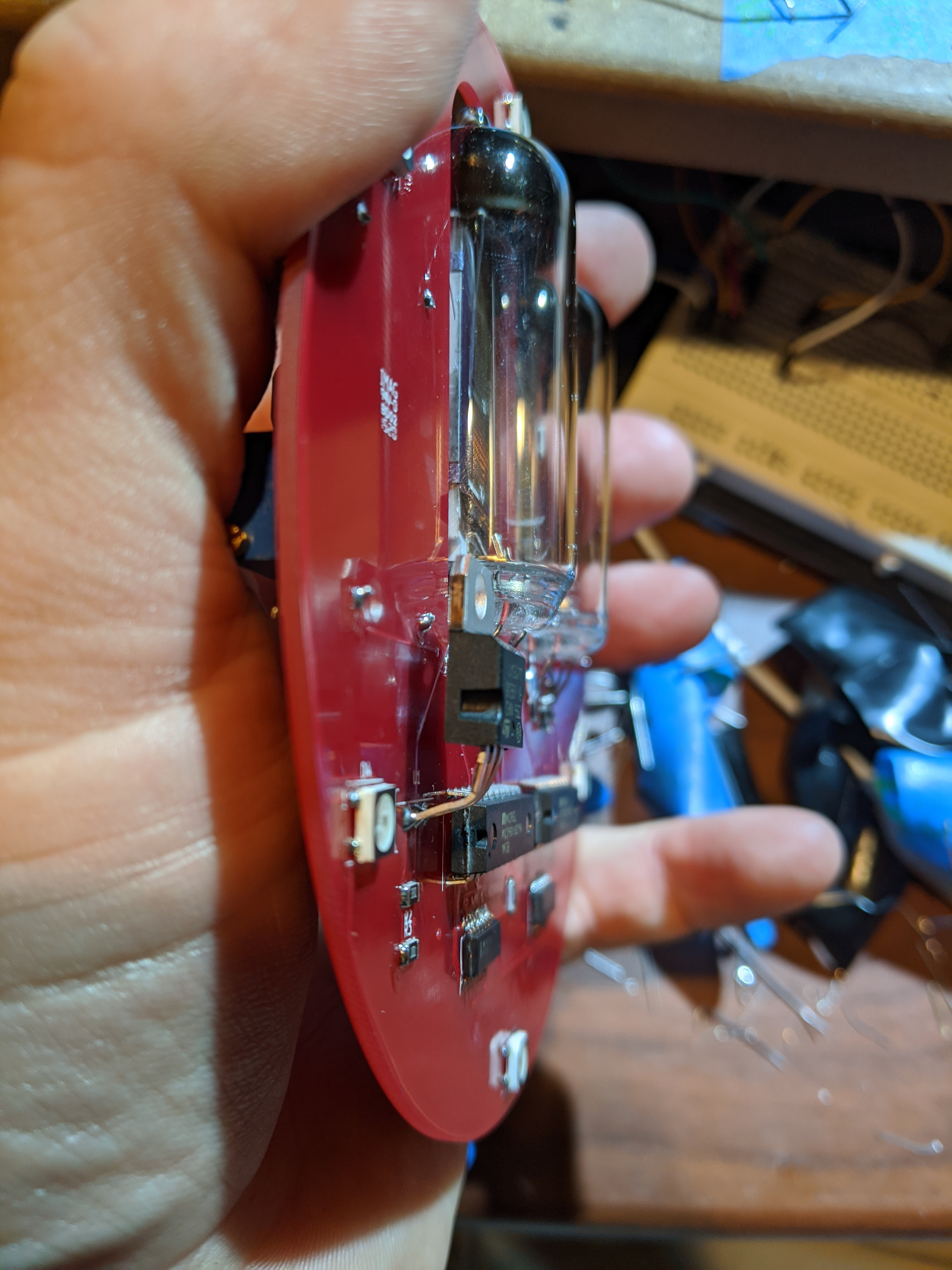
Step 9 (1.5v Regulation): For this part, you’ll need the voltage regulator. Solder on the regulator by taking the very end of the leads and bending them so the chip doesn’t rest flat against the board, but hovers. This is so that it can vent some heat.
Now, power it up! 5VDC USB, 1.5 amps at most is what this seems to be happy with. The tubes should start counting up as the WiFi connection is made, then they’ll turn on the LEDs. If things don’t seem to work, check your solder joints (reflow) and look for shorts.
Feel free to contact me on twitter (@dntlookbehindu) or email (russell@handorf.com) if you have any questions. This is a living document after all. Thank you!
|